VG3 Software Manual
Software Update Log
Software Introduction
VisionGroup3 Vision Software Platform
Menu Bar
Quick Options Preview
Flow Tree and Global Flow Tree
Function Tree
Software Version Description
Function Addition Tree
Function Information
Image Display Area
AI Model Tree
Global Variable Tree
Camera
Coordinate System Tree
Hardware Communication Configuration
Usage and Troubleshooting of Various Communication Simulation Software
Hardware Management Device Connection Test
String Monitor Operation
Digital IO Monitor Operation
Register Monitor Operation
Image Processing
Image Acquisition and Display
Camera Image Acquisition
Camera Label Image Acquisition
Display Image
Window Clear
Read Camera Image
Video Processing
Video Reading
Video Download
Video Acquisition
Video Generation
Color Detection
Color Image Cropping
Color Selection
KNN Color Selection
Color Conversion
Block Sequence Detection
Color Blob Detection
Category Color
Image Preprocessing
Image Cropping
Image Merge
Image Ring Unfold
Image Filtering
Image Transformation
Camera Distortion Calibration
Perspective Distortion Calibration
Image Correction
Region Processing
Geometry to Region
Region Transformation
Region Screening
Region Operation
Blob Region
Region Creation
Region Generation
Simple Detection
Blob Detection
Blob Multi-Region Detection
Image Contrast
Image Brightness
Line Burr Detection
Circular Burr Detection
Pixel Difference Detection
Positioning and Measurement
Matching
Feature Matching
Optimized Feature Matching
Single Target Template Matching
Multi-Template Feature Matching
Geometric Extraction
Extract Line
Extract Circle
Extract Arc
Extract Ellipse
Edge Extraction
Extract Parallel Lines
Line Intersection
Extract Quadrilateral
Point-Line Caliper
Line-Line Caliper
Edge Distance Counting
Measurement Calibration
Farthest Nearest Point Extraction
Geometric Calculation
Custom Point
Custom Line
Custom Circle
Custom Pose
Custom Rotated Rectangle
Custom Coordinate System
Custom Rectangle Array
Line-Line Intersection
Line-Line Angle
Angle Bisector
Line-Line Distance
Point-Point Distance
Point-Line Distance
Point-Circle Distance
Point-Circle Tangent
Line-Circle Distance
Line-Circle Intersection
Circle-Circle Intersection
Position Correction
Point + Angle Correction
Two-Point Position Correction
Two-Line Position Correction
Positioning Guide
Camera Calibration
Long Radius Calibration (Auto)
Long Radius Calibration (Manual)
Camera Simple Calibration
N-Point Calibration
Calibration Transfer
Calibration Verification
Calibration Reference
Calibration Calculation
Calibration Conversion
Camera Calibration Conversion
Mapping
Mapping Reference
Mapping Conversion
Mechanical Transfer
UVW Calculation
Learn Reference Target
Single Camera Pick
Single Camera Pick (Eye-in-Hand)
Single Camera Pick and Place
Single Camera Correction
Multi-Camera Correction
Dual Camera Alignment
Mechanical Point Alignment
Multi-Camera Alignment
Mechanical Point Alignment (Weight)
Multi-Region Alignment
Identification Tools
Code Reading Tool
1D Barcode Quick Recognition
2D Barcode Quick Recognition
All Type Code Reading
Barcode Grading (AI)
Character Recognition
Matching Character Recognition
Deep Learning
Detection
Object Detection (AI)
Rotated Object Detection (AI)
Human Keypoint Detection[AI]
Segmentation
Image Segmentation AI
Classification
Image Classification[AI]
Recognition
Character Recognition[AI]
Auxiliary Tools
AI-Assisted Annotation
Auxiliary Tools
Control Statements
Flow Unit
Conditional Detection
Complex Condition Detection
Loop Detection
Break
Continue
Combo Box
Flow Delay
Jump Module
Flow Reset
Stop Software
Start Detection
Pause Software
Process Trigger
Async Flow Trigger
Recipe switching
Loop Position Filtering
System Tool
DEBUG INFO
System Time
System Info
Sequence Tools
Data Sequence
Data Sequence Calculation
Continuous state change
Continuous status confirmation
Spatial Displacement Change
Sequence Action
Mathematics and Data
Logical relationship
Arithmetic Operations
Relational Judgment
Absolute Value
Relative Value
Trigonometric Functions
Integer Bitwise Operation
Data Processing
Data Summary
Label Filters
Rotated Label Filtering
Multi-ROI Rotated Label Filtering
Data Calculation
Lua Script Tool
Variable Processing
Linear Variable Creation
Linear Variable Writing
Linear Variable Array Insertion
Linear Variable Array Deletion
Linear Variable Array Value Setting
Global Variable Reading
Global Variable Writing
Global Variable Invalidation
Global Variable Array Insertion
Global Variable Array Deletion
Global Variable Array Value Setting
Global Image Array Preview
Data Binding
Data Unbinding
Array and String
Array Insert
Array Slice
Array Remove
Array Get Value
Array and Data Concatenation
String Split/Conversion
Data to String
String to Data
String Split
String Find
String Substring
Result Analysis
Display Data
Display Array Data
Save Image
Statistical Counting
Display Result on Image
Display Results on Window
Detection Screenshot
Hardware Control
String Communication Read
String Command Control
String Communication Write
Register Communication Read
Register Communication Write
Register Command Control
Siemens DB Block Read
Siemens DB Block Write
Light Controller Control
Digital Input Read
Digital Output Read
Wait for Digital Input
Wait for Digital Output
Digital Output Write
Voice Broadcast
Motion Control
Axis Motion
Stop Axis
Wait for Axis Stop
Set Axis Parameters
Axis Enable
Multi Axis Motion
AI Trainer
AI Trainer Operation Guide
Deep Learning Labeling Principles and Details
Run Interface Edit
Enter Design Interface
Understanding Interface Composition
Object List
Main Menu
Others Design Window Property List Event Script
Widget List
Image Widget
Run Control Widget
Button Widget
Status Monitor Widget
Label Widget
Condition Label Widget
BOOL Setting Widget
Integer Setting Widget
Float Setting Widget
String Setting Widget
Dropdown Setting Control Widget
Integer Slider Widget
Float Slider Widget
Container Widget
Combo Box Widget
Tab Widget
Vertical Layout Widget
Horizontal Layout Widget
Vertical Spacer Widget
Horizontal Spacer Widget
Login Widget
Image Box Widget
Log Widget
Pie Chart Widget
Bar Line Chart Widget
Static Table Widget
Dynamic Table Widget
Circular Progress Widget
Preview Mode
Script Mode
Run Mode
Custom Logo
Software FAQ
How to Solve Global Camera Fly Shooting Smear Problem
Maximize Graphics Card Performance Settings
Method to Enable Virtual Memory
Vision Software Freeze Troubleshooting Steps
Secondary Development
VisionGroup3 CSharp Secondary Development Manual
VG3 SDK Development Guide V1.0 Cpp
VG3 Module Plugin Development
本站点使用 MrDoc 构建
-
+
首页
Camera
# Camera 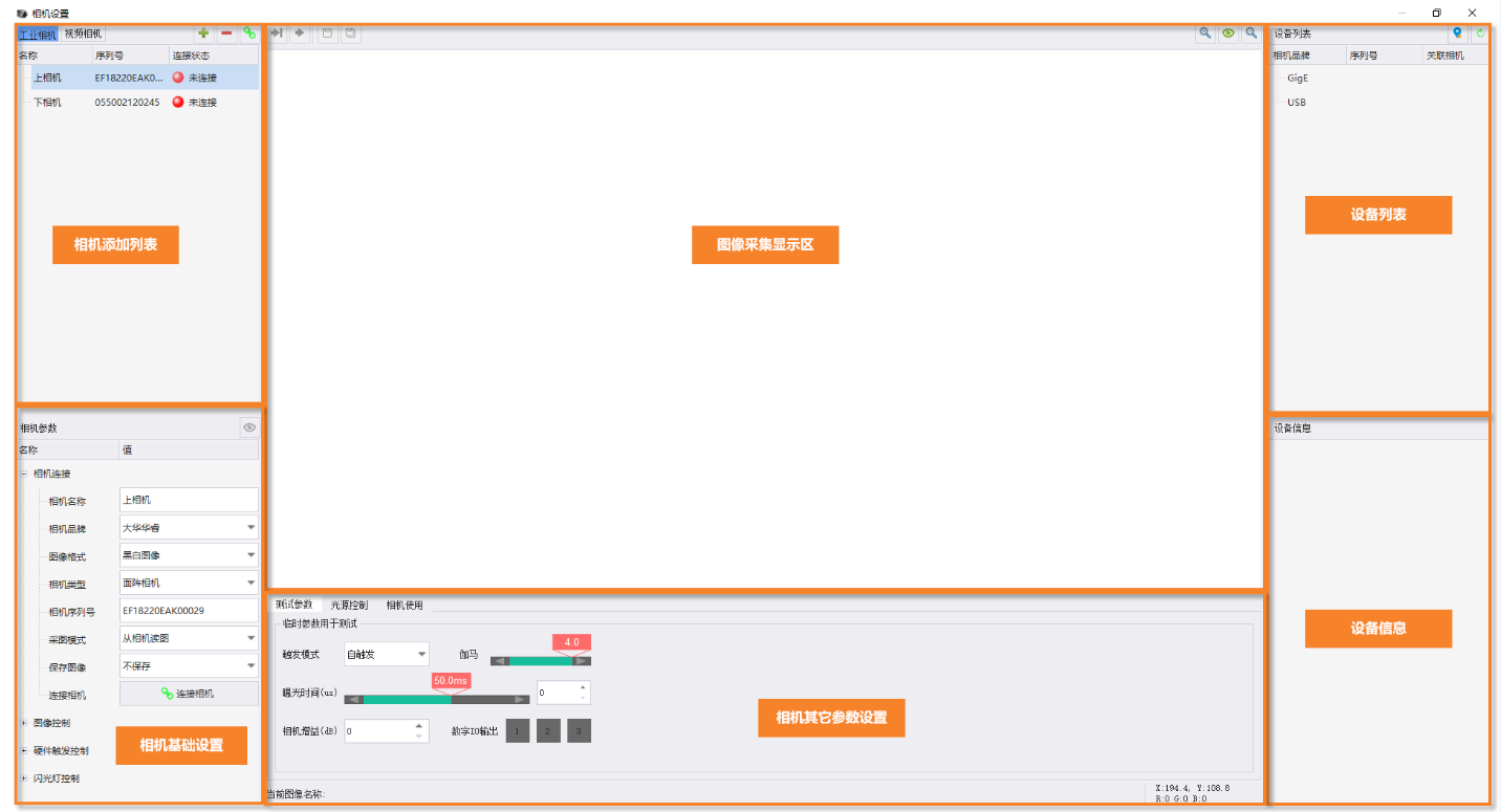 ## Camera Add List 1. Camera management includes two types: Industrial Camera and Video Camera. 1. Industrial Camera Supported Brands: 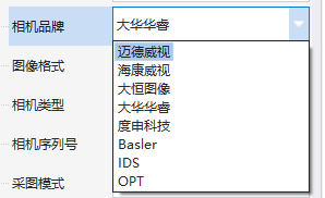 2. Video Camera Supported Brands: * Jovision (Zhongwei Shiji) 2. Camera Operations  * Add Camera * Delete Camera * Disconnect or Connect Camera ## Industrial Camera Basic Settings *(Focus on commonly used parameters)* 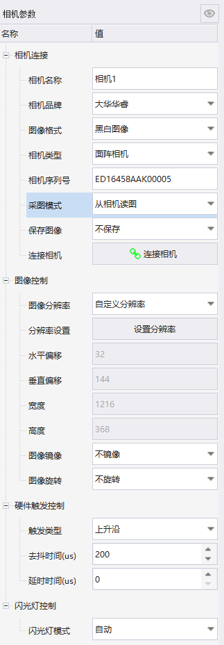 ### Camera Connection 1. **Camera Type: Area Scan Camera, Line Scan Camera** * **Area Scan Camera:** Like a regular phone/DSLR camera, it captures the entire picture instantly with a "click". It produces a complete 2D rectangular image. * **Line Scan Camera:** Like a flatbed scanner or photocopier, it uses an extremely thin photosensitive line to scan the picture row by row from top to bottom, and then "stitches" each row of images together to obtain a complete 2D image. 2. **Camera Serial Number:** If there are many cameras in the device list, you need to fill in the camera serial number here to bind successfully. * **Image Acquisition Mode: Read Image from Camera, Read Image from Disk** * **Read Image from Camera:** Select this mode for formal inspection. > In this mode, users can perform image control, hardware trigger control, and flash control based on the situation. * **Read Image from Disk:** If there is no real camera or for simulation debugging by developers, you can select this mode. > Selecting this mode will directly load all images in the folder on the hard disk into other parameter setting areas of the camera. > In this mode, there is no need to set image control, hardware trigger control, and flash control. ### Image Control 1. **Image Resolution:** Original Resolution and Custom Resolution * Custom Resolution: Users can crop the image here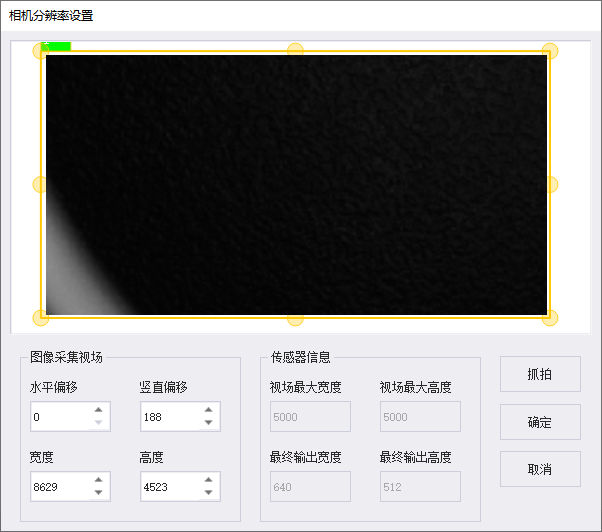 * Image Mirror: No Mirror, X Mirror, Y Mirror, XY Mirror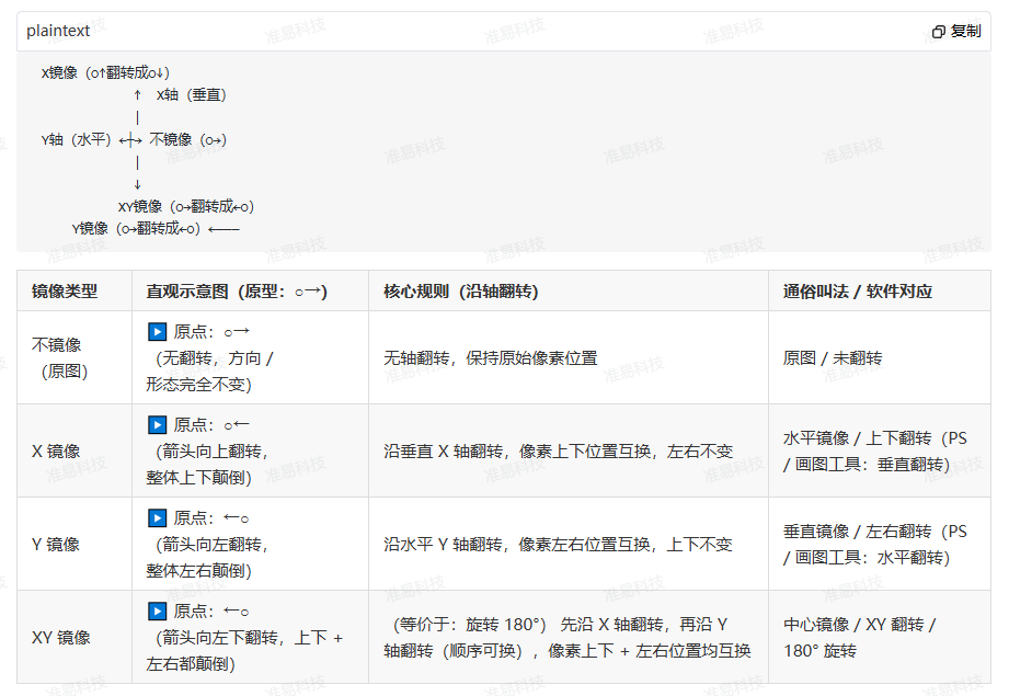 ### Hardware Trigger Control 1. Hardware Trigger Type: Rising Edge, Falling Edge, High Level, Low Level > Core Basis: Intuitive Understanding of Level and Transition > Low Level (L): IO port voltage is 0V (Signal "Disconnected / None" state); > High Level (H): IO port voltage is 24V (Signal "Connected / Present" state); > Transition: The instantaneous process of level changing from L→H or H→L (Non-continuous, just a time point); > Continuous: The time period during which the level remains L or H unchanged (Status remains as long as it lasts). 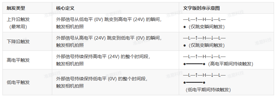 ## Industrial Camera Other Parameter Settings ### Real Acquisition Mode, Providing Test Parameters, Light Source Control 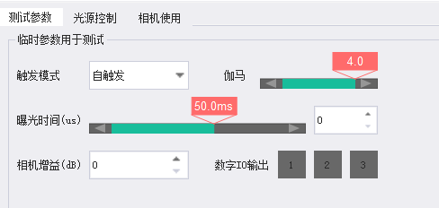 * Trigger Mode: Self-Trigger, Software Trigger, Hardware Trigger >i **Trigger Mode Description:** > > Self-Trigger: In this mode, the camera automatically captures images, mostly used for projects requiring continuous photo inspection. > > Software Trigger: In this mode, the software needs to send a trigger command (Camera aGrabSave) to the camera first to capture an image. > > Hardware Trigger: This mode requires connecting the camera's IO trigger line, and the corresponding thread trigger mode must be set to self-trigger. The camera can only capture images when there is a set signal on the camera IO trigger line; for other wiring methods, please select Software Trigger. * Gamma: Gamma adjusts the brightness display of the image by twisting the ratio of gray values to fit human eye perception or preserve original linear data for machine algorithms. Industrial camera gamma values generally support custom adjustment from 0.1 to 4.0, and some cameras preset common values (such as 0.45, 0.5, 1.0, 2.2). The core is divided into three cases: γ=1, γ<1, γ>1. Each value corresponds to a clear industrial usage scenario with no ambiguity. | Gamma Value Setting | Core Mapping Effect | Image Visual Performance | Core Applicable Scenarios | |------------|--------------|--------------|--------------| | γ=1 (Default Linear) | Input = Output, no non-linear correction, retains sensor original linear gray data | Image is dark, shadow details are invisible to the naked eye, but gray value corresponds 1:1 to actual light intensity | Machine vision algorithm processing (defect detection, dimension measurement, positioning, OCR, gray analysis) — The most core usage scenario for industrial cameras | | γ<1 (e.g., 0.4/0.5/0.8) | Shadow gray values are amplified, highlight gray values are compressed (gray values in low brightness range are more dispersed) | Image is brightened overall, shadow details are clearly visible, highlight details are slightly lost | Human visual observation/monitoring (low light environment, manual inspection of shadow defects, observation of dark textures on metal workpieces) | | γ>1 (e.g., 1.2/1.5/2.2) | Highlight gray values are amplified, shadow gray values are compressed (gray values in high brightness range are more dispersed) | Image is darkened overall, highlight details are clearly visible, shadow details are slightly lost | Human visual observation/monitoring (strong light environment, high reflective surface, manual inspection of highlight defects, such as glass scratches, metal highlight area flaws) | * Exposure Time: Sensor light reception duration, linearly controls brightness, directly affects motion blur. Set this parameter first for industrial debugging. * Camera Gain: Gain is brightness compensation at the electrical signal level. It only amplifies existing signals (including noise) and does not increase the actual light received by the sensor; gain increases brightness but also noise/speckles, and reduces gray uniformity. Minimize use in industrial debugging. Prioritize exposure adjustment. * Digital IO Output: Used with digital IO output module for testing. ### Simulation Mode, Preview Image, Light Source Control  ### Light Source Control Parameters 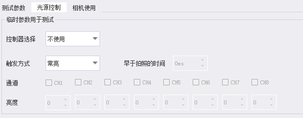 The light source control here only applies when a real camera is connected. For simulation cameras, the parameter configuration here is invalid. * Controller Selection: Supports 7 light source controllers. * Trigger Mode: Always On, Software Trigger. * Time Earlier Than Shooting: Set how many ms earlier than shooting to turn on the light source. * Supports 8 light source channels, and the brightness of each channel can be set individually. ### Other Notes >i **Other Notes** > > 1. Set the static IP address of the host network card. > 2. Turn off the firewall and enable Jumbo Packet on the host network card. > 3. Install the driver for the camera used. > 3.1 For MindVision cameras, please install version 2.1.10.166 or above. > 3.2 For Hikvision cameras, please install version 3.3.1_201207 or above. > 3.3 For Daheng Imaging cameras, please install version 2.6.2107.8081 or above. > 3.4 For Dahua Huarui cameras, please install version 2.3.1_Build20210928 or above. > 3.5 For Do3think cameras, please install DS_DRIVERS_V2.26.59.25 or above. > 3.6 For Basler cameras, please select Basler_pylon_7.3.0.27189 version and install using developer mode. > 3.7 For IDS cameras, please select ids_peak_2.0.1.1 version. At this time, the software only supports uEye+ series cameras. > If using uEye series cameras, please contact the supplier to install ids_peak_2.0.1.1 according to the operation document before installing the driver. > 4. Use the camera driver to connect the camera and set the camera IP address and host IP address to other IP addresses in the same network segment. > 5. Close the camera driver, then open this software to connect the camera and set camera parameters to normally use the camera for image acquisition. > 6. Color cameras currently only support Bayer GR 8/Bayer RG 8/Bayer GB 8/Bayer BG 8/RGB 8 formats. > Note: Do not use switches or routers to connect network port cameras and computer hosts. Instead, connect directly via network cable to avoid exceptions. ## Video Camera Basic Settings 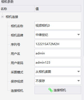 * Video cameras require a username and password to connect. * Acquisition mode can also select Read Image from Camera and Read Image from Disk. * Supports synchronous video saving when reading images. ## Video Camera Other Parameter Settings ### Image Parameters (Key Parameter Introduction) 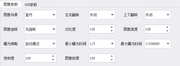 ### OSD Parameters (Key Parameter Introduction) 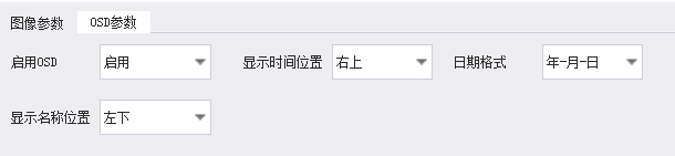 ## Device List This lists all available camera devices for users to add. ## Device Information This displays detailed information about the camera selected by the user in the device list. ## Image Acquisition Display Area * In Real Acquisition Mode, captured images are displayed in this area. * In Simulation Mode, original images are displayed in this area. * Acquisition Operations  * Single Acquisition * Continuous Acquisition * Single Save * Continuous Save * Saved images will be stored in VisionGroup3\CameraImage under the VG3 installation path. --- Click here to jump to the corresponding Chinese manual page: [Camera](/doc/323)
唐红
2026年3月12日 11:52
转发文档
收藏文档
上一篇
下一篇
手机扫码
复制链接
手机扫一扫转发分享
复制链接
Markdown文件
PDF文档(打印)
分享
链接
类型
密码
更新密码