VG3 Software Manual
Software Update Log
Software Introduction
VisionGroup3 Vision Software Platform
Menu Bar
Quick Options Preview
Flow Tree and Global Flow Tree
Function Tree
Software Version Description
Function Addition Tree
Function Information
Image Display Area
AI Model Tree
Global Variable Tree
Camera
Coordinate System Tree
Hardware Communication Configuration
Usage and Troubleshooting of Various Communication Simulation Software
Hardware Management Device Connection Test
String Monitor Operation
Digital IO Monitor Operation
Register Monitor Operation
Image Processing
Image Acquisition and Display
Camera Image Acquisition
Camera Label Image Acquisition
Display Image
Window Clear
Read Camera Image
Video Processing
Video Reading
Video Download
Video Acquisition
Video Generation
Color Detection
Color Image Cropping
Color Selection
KNN Color Selection
Color Conversion
Block Sequence Detection
Color Blob Detection
Category Color
Image Preprocessing
Image Cropping
Image Merge
Image Ring Unfold
Image Filtering
Image Transformation
Camera Distortion Calibration
Perspective Distortion Calibration
Image Correction
Region Processing
Geometry to Region
Region Transformation
Region Screening
Region Operation
Blob Region
Region Creation
Region Generation
Simple Detection
Blob Detection
Blob Multi-Region Detection
Image Contrast
Image Brightness
Line Burr Detection
Circular Burr Detection
Pixel Difference Detection
Positioning and Measurement
Matching
Feature Matching
Optimized Feature Matching
Single Target Template Matching
Multi-Template Feature Matching
Geometric Extraction
Extract Line
Extract Circle
Extract Arc
Extract Ellipse
Edge Extraction
Extract Parallel Lines
Line Intersection
Extract Quadrilateral
Point-Line Caliper
Line-Line Caliper
Edge Distance Counting
Measurement Calibration
Farthest Nearest Point Extraction
Geometric Calculation
Custom Point
Custom Line
Custom Circle
Custom Pose
Custom Rotated Rectangle
Custom Coordinate System
Custom Rectangle Array
Line-Line Intersection
Line-Line Angle
Angle Bisector
Line-Line Distance
Point-Point Distance
Point-Line Distance
Point-Circle Distance
Point-Circle Tangent
Line-Circle Distance
Line-Circle Intersection
Circle-Circle Intersection
Position Correction
Point + Angle Correction
Two-Point Position Correction
Two-Line Position Correction
Positioning Guide
Camera Calibration
Long Radius Calibration (Auto)
Long Radius Calibration (Manual)
Camera Simple Calibration
N-Point Calibration
Calibration Transfer
Calibration Verification
Calibration Reference
Calibration Calculation
Calibration Conversion
Camera Calibration Conversion
Mapping
Mapping Reference
Mapping Conversion
Mechanical Transfer
UVW Calculation
Learn Reference Target
Single Camera Pick
Single Camera Pick (Eye-in-Hand)
Single Camera Pick and Place
Single Camera Correction
Multi-Camera Correction
Dual Camera Alignment
Mechanical Point Alignment
Multi-Camera Alignment
Mechanical Point Alignment (Weight)
Multi-Region Alignment
Identification Tools
Code Reading Tool
1D Barcode Quick Recognition
2D Barcode Quick Recognition
All Type Code Reading
Barcode Grading (AI)
Character Recognition
Matching Character Recognition
Deep Learning
Detection
Object Detection (AI)
Rotated Object Detection (AI)
Human Keypoint Detection[AI]
Segmentation
Image Segmentation AI
Classification
Image Classification[AI]
Recognition
Character Recognition[AI]
Auxiliary Tools
AI-Assisted Annotation
Auxiliary Tools
Control Statements
Flow Unit
Conditional Detection
Complex Condition Detection
Loop Detection
Break
Continue
Combo Box
Flow Delay
Jump Module
Flow Reset
Stop Software
Start Detection
Pause Software
Process Trigger
Async Flow Trigger
Recipe switching
Loop Position Filtering
System Tool
DEBUG INFO
System Time
System Info
Sequence Tools
Data Sequence
Data Sequence Calculation
Continuous state change
Continuous status confirmation
Spatial Displacement Change
Sequence Action
Mathematics and Data
Logical relationship
Arithmetic Operations
Relational Judgment
Absolute Value
Relative Value
Trigonometric Functions
Integer Bitwise Operation
Data Processing
Data Summary
Label Filters
Rotated Label Filtering
Multi-ROI Rotated Label Filtering
Data Calculation
Lua Script Tool
Variable Processing
Linear Variable Creation
Linear Variable Writing
Linear Variable Array Insertion
Linear Variable Array Deletion
Linear Variable Array Value Setting
Global Variable Reading
Global Variable Writing
Global Variable Invalidation
Global Variable Array Insertion
Global Variable Array Deletion
Global Variable Array Value Setting
Global Image Array Preview
Data Binding
Data Unbinding
Array and String
Array Insert
Array Slice
Array Remove
Array Get Value
Array and Data Concatenation
String Split/Conversion
Data to String
String to Data
String Split
String Find
String Substring
Result Analysis
Display Data
Display Array Data
Save Image
Statistical Counting
Display Result on Image
Display Results on Window
Detection Screenshot
Hardware Control
String Communication Read
String Command Control
String Communication Write
Register Communication Read
Register Communication Write
Register Command Control
Siemens DB Block Read
Siemens DB Block Write
Light Controller Control
Digital Input Read
Digital Output Read
Wait for Digital Input
Wait for Digital Output
Digital Output Write
Voice Broadcast
Motion Control
Axis Motion
Stop Axis
Wait for Axis Stop
Set Axis Parameters
Axis Enable
Multi Axis Motion
AI Trainer
AI Trainer Operation Guide
Deep Learning Labeling Principles and Details
Run Interface Edit
Enter Design Interface
Understanding Interface Composition
Object List
Main Menu
Others Design Window Property List Event Script
Widget List
Image Widget
Run Control Widget
Button Widget
Status Monitor Widget
Label Widget
Condition Label Widget
BOOL Setting Widget
Integer Setting Widget
Float Setting Widget
String Setting Widget
Dropdown Setting Control Widget
Integer Slider Widget
Float Slider Widget
Container Widget
Combo Box Widget
Tab Widget
Vertical Layout Widget
Horizontal Layout Widget
Vertical Spacer Widget
Horizontal Spacer Widget
Login Widget
Image Box Widget
Log Widget
Pie Chart Widget
Bar Line Chart Widget
Static Table Widget
Dynamic Table Widget
Circular Progress Widget
Preview Mode
Script Mode
Run Mode
Custom Logo
Software FAQ
How to Solve Global Camera Fly Shooting Smear Problem
Maximize Graphics Card Performance Settings
Method to Enable Virtual Memory
Vision Software Freeze Troubleshooting Steps
Secondary Development
VisionGroup3 CSharp Secondary Development Manual
VG3 SDK Development Guide V1.0 Cpp
VG3 Module Plugin Development
本站点使用 MrDoc 构建
-
+
首页
Long Radius Calibration (Manual)
## Long Radius Calibration (Manual) Calculates the correspondence between the image coordinate system and the mechanical coordinate system, and generates a calibration file. ## Module Principle By manually inputting the movement coordinates and inputting the image coordinates corresponding to the robot arm movement, the calibration relationship between the image pixel coordinates and the real-world coordinates is established and saved in the global variables. The mechanical point and image point data are acquired externally (image points are usually obtained by acquiring feature points through Optimized Feature Matching). Calibration only has XYR, XR, YR types with angles. ## Usage Method ### Pre/Post-Sequence Modules Camera image acquisition, Optimized Feature Matching to acquire image point data, Thread Variable Writing to mechanical point array, run multiple times to generate calibration. The output of Camera Calibration is the mechanical point that needs to be reached next time. 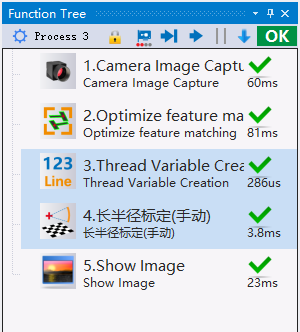 ## Parameter Configuration Description 【Mechanical Parameters】 Set the coordinates of mechanical movement, and obtain image coordinates through input images.<br> Note: In calibration mode, the first picture taken is not included in the calculation; in simulation mode, the first photo will be used as the first point of the image points. 【Calibration Group】 Select the corresponding coordinate system group, and the calibration data will be recorded in the calibration file under this coordinate system group. The coordinate system group must be set in the Coordinate System Calibration in Global Data Management. 【Calibration File】 Select the calibration file under the corresponding coordinate system group, and the calibration data will be recorded in this file. (The calibration file must be set in the Coordinate System Calibration in Global Data Management. First add a coordinate system group, then drag the camera and robot to the window under the corresponding coordinate system group, select the connection line to connect the two icons, and the calibration file can be generated)<br> 【Save Image】 Save the reference image. Mechanical Model: 【XYR】 Mechanical structure XY axes can translate and rotate.<br> 【XR (Y Separated)】 Mechanical structure only has X-axis translation and can rotate, Y-axis structure is separated.<br> 【YR (X Separated)】 Mechanical structure only has Y-axis translation and can rotate, X-axis structure is separated.<br> Photographing Method:<br> 【Eye-to-Hand】 The camera is installed in a fixed position and does not shift or rotate with the machine.<br> 【Eye-in-Hand】 The camera is fixedly installed on the mechanical rotation axis and shifts and rotates with the machine.<br> #### Mechanical Parameters<br> 【Mechanical Rotation Radius】 The physical distance from the rotation center to the feature matching point. Just input an approximate value to improve calculation speed.<br> 【Coordinate System Type】 Determine the coordinate system type of the robot arm.<br> 【Feature Point Angle】 Input the approximate angle of the feature point on the robot arm. Just input an approximate value to improve calculation speed.<br> 【Error】 The maximum error threshold between calibration data and calculation data on the mechanical axis.<br> 【Run Count】 Total number of calibration runs, minimum is 6. Calculate and generate calibration after running the set number of times. Movement requires changes in all xyr directions.<br> 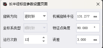 ## Output Description 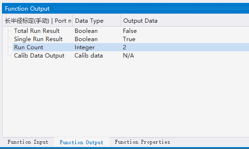 The total run result outputs true after the calibration is successful, otherwise false. The single run result outputs the run result of each photographing movement. When calibration generation fails, both the total run result and the single output are false. ## Precautions 1. When using a bottom camera, X-axis mirroring is required. 2. The height of the plane for calibration needs to be the same as the height during use, otherwise there will be errors. 3. In normal mode (calibration mode), the first image of camera calibration is not included in the calculation, and the camera needs to take one more photo to complete the calibration. 4. Movement requires changes in all xyr directions. ## Problem Solving Build the following flow to test the accuracy of the calibration in xy directions. Move the matching object 1-10mm, observe whether the calibration conversion result changes correspondingly to test the accuracy. 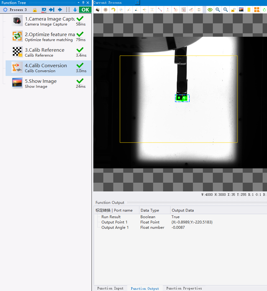 During alignment or picking, when the offset angle increases, causing the xy error to increase correspondingly, it is a calculation error of the calibration rotation center. You can solve the problem by increasing the calibration angle movement (more than 30 degrees). Or by increasing the number of rotations. [【Attachment】Long Radius Calibration (Manual) Example Project.rar](/media/attachment/2026/03/%E9%95%BF%E5%8D%8A%E5%BE%84%E6%A0%87%E5%AE%9A%E6%89%8B%E5%8A%A8%E7%A4%BA%E4%BE%8B%E5%B7%A5%E7%A8%8B.rar) --- Click here to jump to the corresponding Chinese manual page: [Long Radius Calibration (Manual)](/doc/127)
唐红
2026年3月13日 09:26
转发文档
收藏文档
上一篇
下一篇
手机扫码
复制链接
手机扫一扫转发分享
复制链接
Markdown文件
PDF文档(打印)
分享
链接
类型
密码
更新密码